The PiKVM is really a great project. I started thinking about getting one during a period when one of my rackmount servers decided to start misbehaving, and was frequently requiring the connection of a console. And, to give some context for what this meant — my rack is under the stairs, and connecting to it means sitting cross-legged on the floor. That’s OK once in awhile, like a few times per year, not a few times each week! PiKVM to the rescue.
So, I ordered the PiKVM v3 hat and the steel case, which is nice but not really the form factor one wants for an under-the-stairs rack. It wouldn’t fit on a 1U shelf, there’s really no ready-to-go rackmount kit, and I wanted PoE. After some research, I decided to move away from the PiKVM hat and do a DIY-style build using the official Raspberry Pi PoE+ hat, a CSI-2 to HDMI module, and a few other miscellaneous pieces and parts. Being a longtime fan of the RPi and also the Intel NUC, I’m already using several 1U rack mount adapters like this:
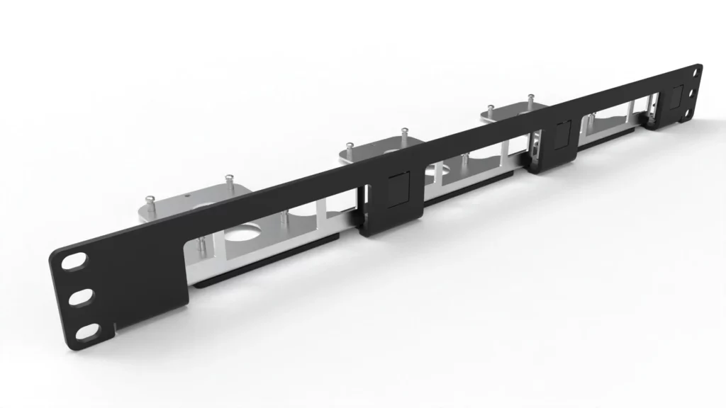
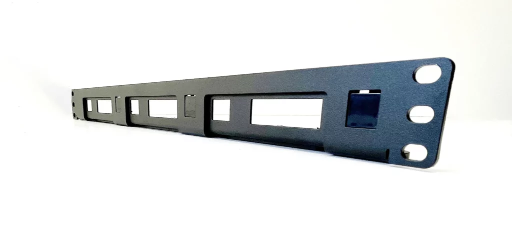
Apparently this particular model, which can accommodate either an RPi or a NUC in any of the 3 positions is end-of-life. However, MyElectronics.nl also makes this unit, which is quite similar and would work equally well for this purpose:
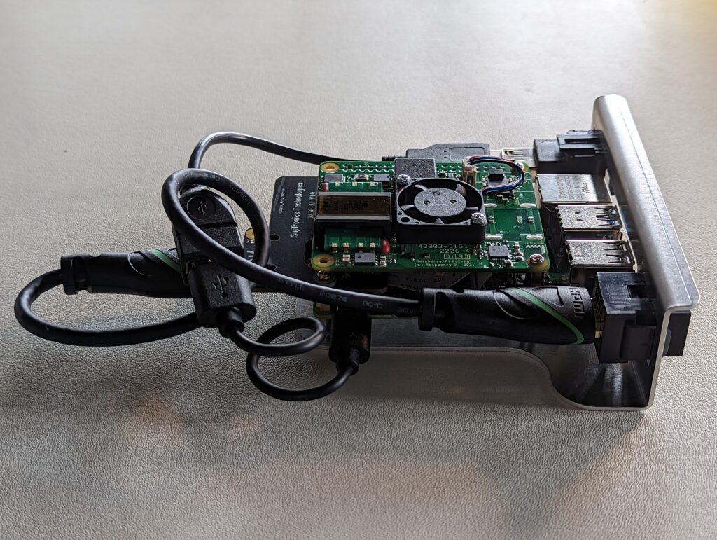
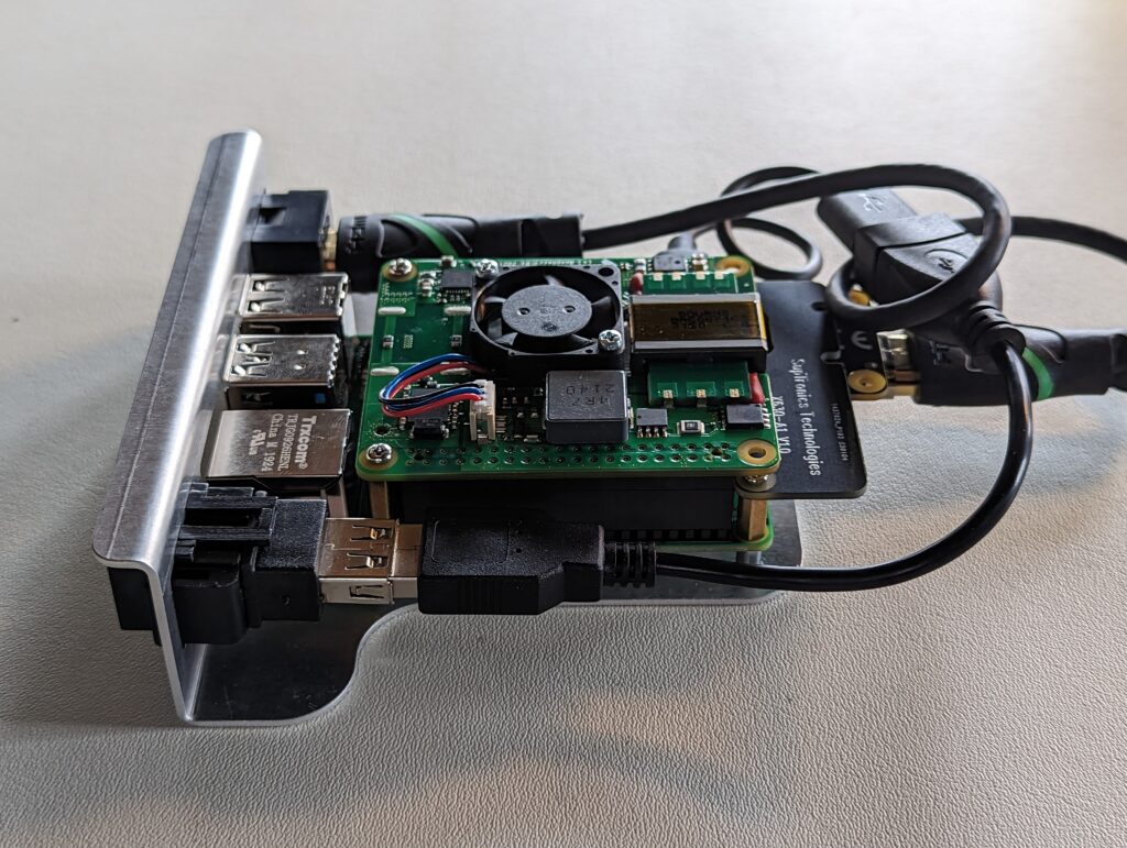
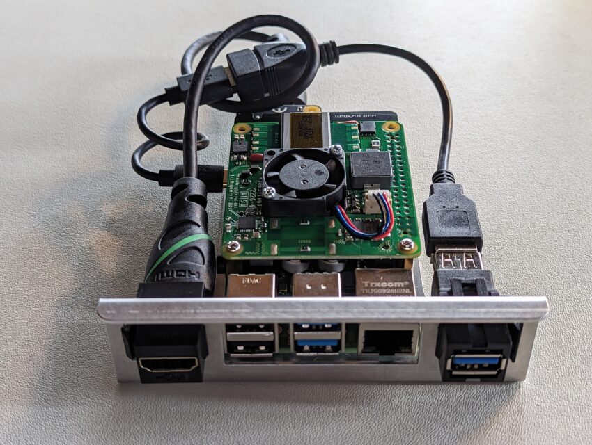
And, to give you an idea of what my build looks like, here are a few pics of the finished product mounted to one of the RPi inserts that fits in the MyElectronics.nl rackmount frame:
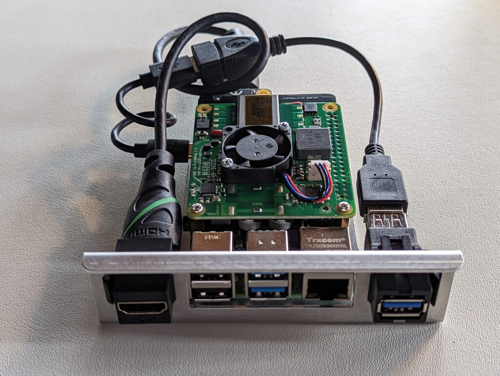
As you can see the end result is pretty slick, and includes front-mounted HDMI-in (the lefthand keystone jack) along with USB-in (the righthand keystone jack). The USB cable coming off the back of the keystone jack is a power-blocking adapter, which is connected to standard USB-C to USB-A cable. The HDMI cable is a high-quality standard 1 footer, that’s connected to a CSI-2 to HDMI board. That CSI-2 board is mounted upside down in between the RPi4 and the PoE+ hat:
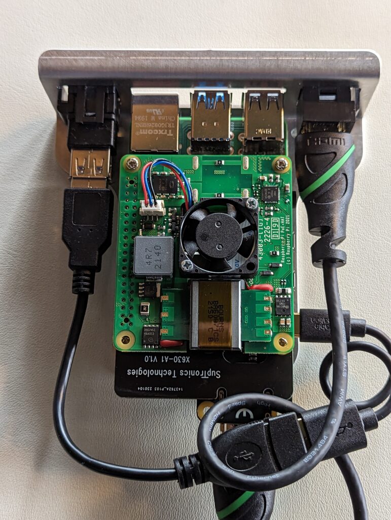
Here’s a general idea of the parts I used, which would likely save you some time if you want to put one together similar to this. You’ll need an RPi4, an official PoE+ hat, and a Pi/NUC rackmount that supports keystone jacks to get the project rolling. In addition, you’ll need the following:
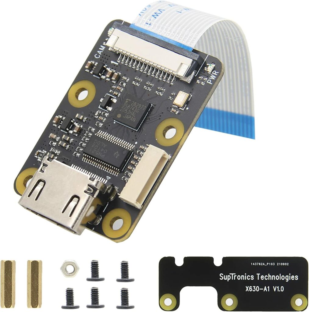
A Geekworm CSI-2 to HDMI module. This one is nice because it includes a daughter board that allows you to secure it in two places:
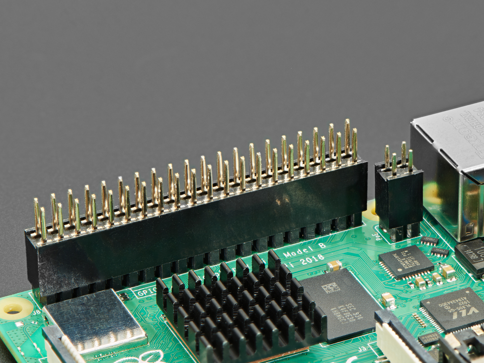
In order to create some space to mount the CSI-2 board between the RPi and the PoE hat, you’ll want some GPIO risers like these. Adafruit sells some that look like these. Note that the 2×2 PoE header riser has very short pins as the matching connector on the PoE+ hat is not pass-through. The 2×20 header riser can either be slightly taller than the PoE riser and not pass-through (as shown in the pic), or you can get one with noticeably longer pins that will pass-through, and give you access to the GPIO pins for other purposes. It’s worth mentioning here that I had to turn my 2×2 header 90 degrees from what you see in this photo to make good contact with the PoE+ female connector. The pins are rectangular, and the 2×2 needs to be turned to match the orientation of the 2×20 pins:
You’ll need some brass standoffs as well. 2x15mm for the front of the RPi, which you’ll attach the PoE hat to — and 1x8mm + 1x10mm for the back of the RPi, to which you’ll attach the CSI-2 mounted upside down. The 8mm standoff goes on the thicker side of the assembled CSI-2 + daughterboard, and the 10mm goes on the thinner side. The standoffs screw through the RPi and into the aluminum bosses on the rackmount RPi “adapter”.
You can find the standoffs in small packs, or get a kit that includes a variety of them. I buy kits like this, so projects aren’t held up by not having the right size stand-off:
I like these from Electronics-Salon: https://www.amazon.com/gp/product/B072N84VM3/

As mentioned previously, the USB cable connected to the keystone jack needs to be of a power blocking type. I ordered the TH3D EZBlocker, but you can also get one on Amazon called the PortaPow USB Power Blocker which would do the same job. From there, you can use any (short) USB-C male to USB-A male cable to connect to the USB-C port on the RPi.
You’ll need HDMI and USB keystone jacks. I used a VCE HDMI jack and a RiteAV USB3 jack. Both are good quality and snap right into the open spots in the MyElectronics.nl RPi trays/adapters.
So — that’s really all you need. The PoE+ hat doesn’t suffer from the same conflict that the older PoE hat has between the PoE fan controller and the CSI-2 board, plus if your switch can supply 802.11at power you’ll have 25+ watts available to the Pi.

This is lacking the ATX power on / off option isn’t it? Otherwise it looks pretty great, thank you.
No, I didn’t implement the ATX power on/off, as it wasn’t something I needed for this project. If I was to add it in the future, this is likely the set of control boards I would use https://wiki.blicube.com/blikvm/en/atx-guide Alternatively, you could go with this internal card from Blicube https://www.blicube.com/blikvm-v2-pcie The card is externally powered, including via PoE, and allows for all-internal wiring in scenarios where there’s a PCIe slot available in the computer you want to control.